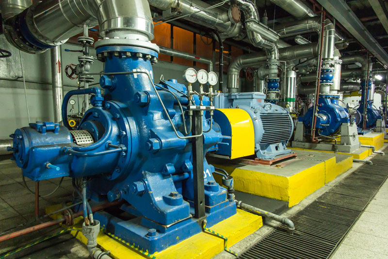
When the whole plant unexpectedly shuts down, then the pump gets attention. A report presented by Occupational Safety and Health Administration (OSHA) shows that most workforce accidents occur when a plant is in an emergency (unscheduled) situation. If you want to increase reliability and reduce the high costs and safety risks associated with emergency shutdowns, adding gauges and managing the data are simple and inexpensive first steps.

Gauges
Gauges will measure pump performance and display the differential pressure across the pump. That information, in conjunction with knowledge of the pump and system curves, will provide plenty of details about the health of the pump and system.
Pump Curves
The pump will operate at the point on its curve where it is intersected by the system curve. As the pump curve changes with impeller size, speed and wear (clearances open up), the system curve changes with wear, process control changes, corrosion and/or marine growth buildup.
10 tips providing guidance for using gauges to achieve better pump life management.
- Gauges are simple and relatively inexpensive. In addition to gauges, end users can adopt more current technology by substituting pressure transducers (digital gauges).
- Two gauges are recommended on the pump, one on the suction and one on the discharge. As a “Plan B,” use one differential pressure gauge. This is better than no gauges at all.
- It is advisable to use a compound pressure gauge or absolute pressure gauge on the suction side.
- It is recommend using absolute pressure gauges to avoid error in calculating the differential pressure.
- Several companies specify that gauge “taps” (penetrations drilled and tapped) be put on the pump flanges. It may be easier and less expensive to have them on the adjacent piping.
- The size of the pipe and the flow rate should be noted and then understand that gauges (transducers) measure pressure, not velocity. Should you place gauges on the adjacent piping, be aware that differences in elevations will need to be compensated to a common datum point, usually the pump (or impeller) centerline.
- A pressure gauge placed four to six pipe diameters downstream of the discharge flange will yield a more accurate head reading. Note that the gauge should be placed before the isolation and check valve to be accurate.
- Many facilities do not use gauges because of issues with vibrations and pressure pulsations. The use of snubbers, loops, capillary tubes and isolation valves is recommended to mitigate the problem.
- It is noted that some plants do not incorporate gauges for a variety of reasons. For those facilities, it’s advisable that at least an isolated/capped or plugged penetration where a gauge, transducer or digital gauge can be installed.
- Select the gauge (transducer) to be in the correct pressure range for the application. Gauges are most accurate in the middle one-third of their total range. Do not forget temperature ratings and compensation in that selection process.
Have Questions? Give Us a Call.
If you ever have a question regarding industrial pumps that you are looking for more information on, never hesitate to call one of our trained experts @ 800.560.7867.
